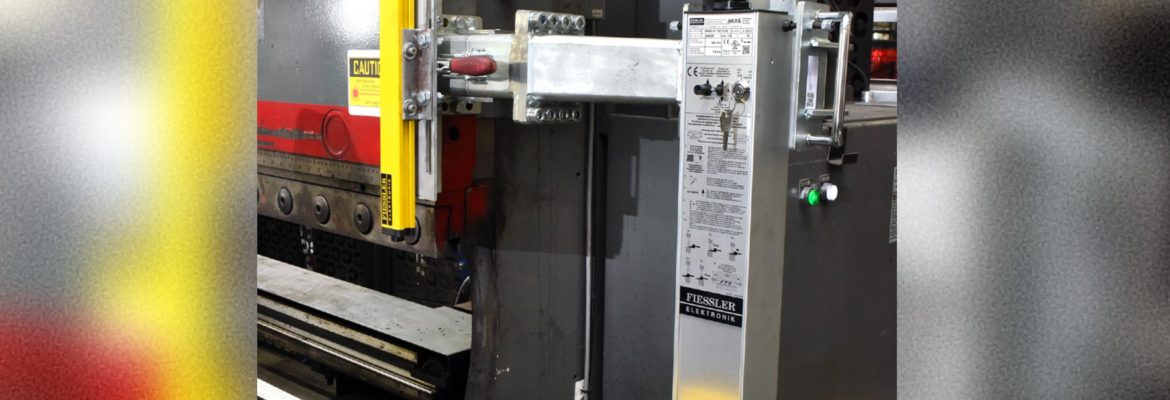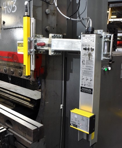
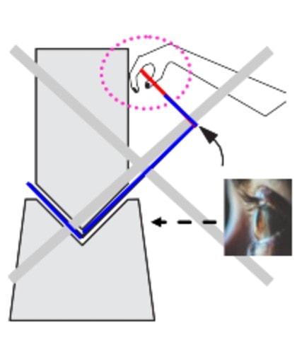
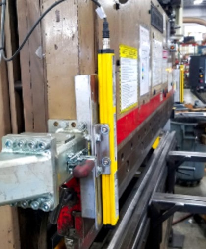
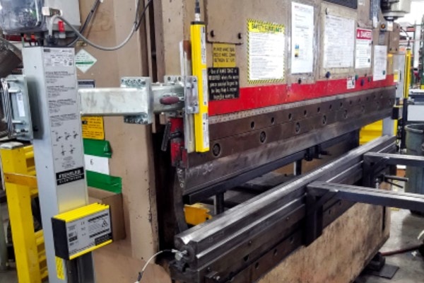
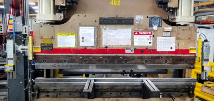
 When forming reverse flanges that fold into the ram face, a secondary safety system mounted to the ram front face, protects the operator by monitoring that “crush zone” area. Shown in red, these accidents occur due to the operator focusing on the part bending in the tooling and not on the part edge folding into the ram.
By using the part drawings the reverse flange should be clearly identified in both shape and dimension.
The area of the ram face is chosen based on how and where the part folds into the ram. The light curtains are adjusted to scan that area. The adjustment of the light curtains to properly monitor the “crush zone” is another part of the press brake setup that is required by the operator.
Should the part be held where fingers or a hand would be between an edge and the ram face it would trigger the system to stop ram movement, preventing an accident.
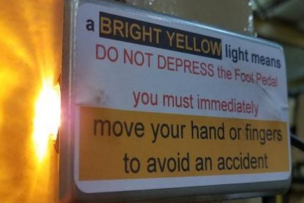 The BRIGHT YELLOW warning light remains solidly lit until he operator releases the foot pedal, or by moving finger(s) or hand(s) to an alternate safer location. Depress the foot pedal to finish forming the part. With the obstruction removed, the light remains off as the ram continues the stroke.
OVERRIDING
If the system is overridden by again depressing the foot pedal, without removing the triggering mechanism, the warning light will stay lit but flash rapidly throughout the stroke as a DANGER alert. This is similar to the Wavy Material override but in the Crush Zone area.
FALSE CRUSH ZONE ALERTS
It is possible that a part profile is of such configuration that the Crush Zone intrusion detection is triggered, the warning light is lit and the ram movement is stopped when no dangerous condition exists. It has been observed that some odd part designs, very thick sheets, and rods can cause the ram to stop and present as though a finger or hand were in the wrong position.
This may be due to exceeding the resolution of the scanning device. In these cases, you may choose that after verifying no dangerous safety condition exists depress the foot pedal, and with the warning light flashing proceed with extreme caution to finish the part.
 |
 |
 |
 |
The “Crush Zone” is defined as the area of the ram face where, by holding the part incorrectly, a hand or finger can be pinched between the part edge and the ram as it folds upward. 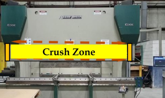 Crush Zone monitoring capability is limited by the beam resolution of the light curtain used for this task. The light curtain selected is dependent upon the design criteria that is defined by the profile of the part being formed as it passes through the scanned area. The operational technology used is not 100% fool proof and must be used with through understanding, caution and operator’s involvement. The ability for this device to help prevent pinch point accidents is also dependent upon the way in which the Crush Zone scanning devices are adjusted or set by the operator to meet the design of the parts being formed.
LEDs and displays
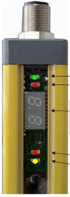
The LEDs and display on the receiver indicate the current operating status.
Outputs (OSSDs) active ……………. green LED comes on when the outputs are energized.
Outputs (OSSDs) inactive ………….. red LED comes on when the outputs are de-energized.
– Indication of operating mode …… for about 2 seconds during power-on.
– Indication of the uppermost interrupted light …….. see below
– Error diagnosis………………………. refer to the chapter on error diagnosis
Adjustment aid and light reserves .. red LED comes on when light reserves have dropped.
Restart interlock ………………………. in the operating mode with restart interlock, the yellow LED comes on when the protective field is clear and the start button is ready for operation.
Display on interruption of a light beam
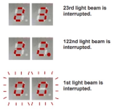
If one or more light beams are interrupted, the number of the uppermost interrupted beam (as seen from the
connecting plug) is displayed.
On light grids comprising more than 99 light beams, the right-hand decimal point also shines if the 122nd beam is interrupted, for instance. If a light beam numbered higher than 200 is interrupted, both decimal points shine.
If the synchronous eye is interrupted (1st light beam as seen from the connecting plug), “0 0” flashes on the display.
Indication of operating mode
The stored operating mode is indicated for about 2 seconds during power-on.
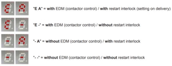
Changing the operating mode
To change the operating mode you have to disconnect the power supply. Then bridge the OSSD2 (6) output with +UB (2) input and connect a button between the Start (1) input and +UB (2) input .

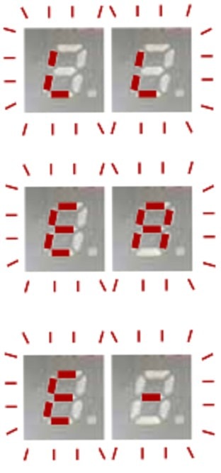 The button at the Start input must be actuated during power-on. “L L” flashes on the display.
The button at the Start input must remains on (min. 2s),until the actual operating mode from the device flashes on the display. You can then release the button.
To select a new operating mode, briefly press the button once again; the selected mode flashes on the display. Each time you shortly press the button, the next operating mode is called up.
If you hold down the button for 2 seconds or longer, the currently displayed operating mode is saved and remains solidly lit on the display.
This procedure (brief actuation of the button) can be repeated as often as necessary. After you have removed the bridge between OSSD2 and +UB and reset the voltage, the saved operating mode becomes effective.
Fault diagnosis
If the light grid detects a faulty connection or an internal error, the adjustment-aid and restart-interlock LEDs flash together with the corresponding error code on the display.
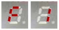 F1 = Incorrect start line
Operating mode with restart interlock: Start input is bridged to +24 VDC.
Operating mode without restart interlock: Bridge from start input to +24 VDC is missing.
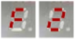 F2 = Incorrect EDM line
Operating mode with EDM: The contactors are not released or the EDM input is bridged to +24 VDC.
Operating mode without EDM: Bridge from EDM input to +24 VDC is missing.
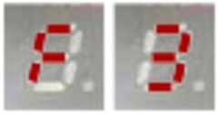 F3 = External transmitter detected
A second light transmitter has been detected in the receiver’s range. To preclude mutual interference between adjacent light curtains, neighbouring systems must be installed in accordance with the instructions.
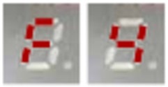 F4 = Error during change of operating mode
The start button was held down too briefly for changing the operating mode during power-on. Or the bridge from OSSD2 to +24 VDC was detached during a change of operating mode.
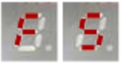 F5 = Internal error
Power-on the device once again. If F5 is still displayed, an internal error has occurred. In this case, the device must be sent in for repair.
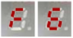 F6 = OSSD error
Short-circuit between one or both OSSDs and +24V, or between the OSSDs.
__________________________________________________________________________________________
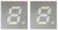 No start possible despite clear light path (display off):
In the operating mode with restart interlock, if the yellow LED does not shine despite intact light beams and the adjustment aid LED is off, it means that the contactors are not released.
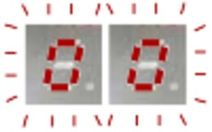 Flashing:
1st light beam is interrupted.
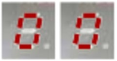 Not flashing:
No blanking (only for BLCT)

